This is not in my wheelhouse. But it is an interesting problem to read about.. I am sure you already used AI to give you some feedback, but for the benefit of other forum readers, I can summarize what I found from Gemini AI.
In flight controller firmware (like ArduPilot or PX4), the “fast loop” (sometimes called the main loop or primary control thread) is the core, high-priority software cycle that handles the immediate, real-time stability of the aircraft.
SENSORS > FILTERING > CONTROL (PID) > ACTUATION
ArduPilot’s fast loop runs inside Copter::fast_loop(). For an older FMUv2 board, this typically clocks at 400Hz by default (SCHED_LOOP_RATE).
The Pixhawk 2.4.8 uses an older processor (designed back in the early 2010s). Trying to push 400 packets of data every single second across that serial connection is like trying to force a firehose of data through a drinking straw. The Pixhawk’s processor gets overwhelmed just handling the data transfer, resulting in dropped packets, timing delays (jitter), and potential crashes.
The Pixhawk 2.4.8 STM32F427VIT6 main processor runs on an ARM Cortex-M4F architecture.
- Clock Speed: It operates at 168 MHz (168 million clock cycles per second).
- Instruction Throughput: Under typical conditions, the Cortex-M4 achieves roughly 1.25 DMIPS/MHz (Dhrystone Millions of Instructions Per Second).
- Total Performance: This gives the hardware a peak processing capacity of approximately 252 MIPS (Million Instructions Per Second).
When you write a custom flight mode class (like ModeAgileTurn), ArduPilot automatically executes your custom run() function inside this fast loop. This gives the exact 400Hz update needed without overloading the processor with communication overhead.
The Windup Trap: During a violent, high-speed agile turn, the drone’s motors might physically maximize their power (saturate) trying to achieve the aggressive turn rate. Because the drone cannot instantaneously match the extreme command, error accumulates. The “I” (Integral) term keeps building up and “winding up” like a compressed spring.
When the turn ends, that wound-up “I” term causes the drone to aggressively overshoot the target, leading to violent wobbling or a crash.
Three ways to fix this in the custom code:
- Freeze the I-term: Tell ArduPilot to stop accumulating past error the moment the agile turn begins.
- Flush the memory: Use a built-in ArduPilot function (
reset_I()) to instantly wipe out any old accumulated error before starting the turn.
- Direct Mixer Override: Bypass ArduPilot’s standard PID calculations entirely and tell the motors exactly how fast to spin based on custom mathematical formulas.
Even if the processor calculates the commands at 400Hz, it still has to physically send those signals to the ESCs. Modern ESCs use a digital protocol called DShot, which is incredibly fast and precise, but requires precise hardware timers inside the microchip.
Because the Pixhawk 2.4.8 is older hardware, its internal timers are shared across its output pins. Pushing high-speed digital DShot signals while the processor is already busy running the custom agile-turning math can overwhelm the chip.
Because it lacks dedicated, independent hardware drivers for every output pin, the main CPU has to manually manage the timing of these digital pulses using bit-banging or heavy DMA (Direct Memory Access) interrupts.
Every time a DShot packet is sent or a telemetry packet returns from the motor, it triggers an “interrupt.” This forces the CPU to instantly pause its current flight math, handle the motor signal, and switch back. At 400Hz across four or more motors, these constant interruptions add massive overhead.
If the drone starts skipping cycles (called loop slips), you will have to downgrade the signal type from digital DShot to high-speed analog PWM (Pulse Width Modulation) or OneShot125, which require less processing power.
To comfortably execute an internal 400Hz control loop , handle advanced state estimators (EKF3), and drive high-speed digital ESC protocols simultaneously without loop slips, you need a flight controller powered by an STM32H7 processor (running at 480MHz with a double-precision Floating Point Unit).
The optimal choices for this architecture are:
- Holybro Pixhawk 6X: Built specifically to modern FMUv6X open standards, this board provides the necessary computational headroom to execute a custom 400Hz flight mode without risking watchdog resets. It features a high-speed onboard Ethernet interface , allowing massive data logging or off-board state synchronization with a companion computer without saturating the standard serial/UART lines.
- CUAV Pixhawk V6X: An excellent alternative option running the same dual-core H7 processor architecture. It relies on a high-performance Cortex-M3 coprocessor to isolate IO processing from the main flight dynamics calculations, ensuring that heavy telemetry streams or custom motor scripts will not cause a single microsecond of lag in the core control loops.
To match the 400Hz refresh rate calculated by the flight controller, you should discard traditional analog PWM and use a modern DShot capable electronic speed controller. A high-performance 4-in-1 ESC running modern 32-bit architecture allows for ultra-low latency, bidirectional communication, and rapid regenerative braking.
- Foxeer Reaper F4 Mini 128k: This ESC utilizes a dedicated F4 processor right on the speed controller board, completely eliminating the processing delays and signal de-sync risks common during high-acceleration turns. It supports up to DShot1200 alongside a 128kHz PWM drive frequency, providing the smoothest possible throttle resolution for transient response research.
- T-Motor P60A V2 4IN1 ESC: Known for its heavy-duty current handling capability, this unit supports DShot2400 and advanced telemetry tracking (delivering exact rotor speeds and thermal data back to the Pixhawk over a single wire). It is ideal for aggressive maneuvering research where high torque spikes and maximum active braking (Damped Light mode) are constantly engaged.
When moving your agile turning research to the suggested H7 hardware running ArduPilot, you can move past baseline workarounds and directly utilize the following firmware code adjustments:
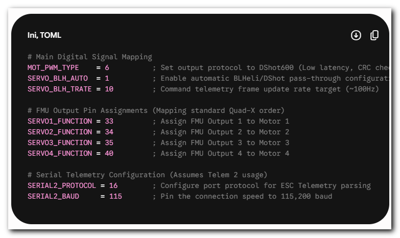
- Activate Bidirectional DShot Telemetry: Configure
MOT_PWM_TYPE = 6 (DShot600) and enable the underlying timer masks. This forces the ESCs to stream precise, hardware-measured motor RPM data directly back to the flight controller over the DShot telemetry lines. You can feed this real-time motor speed matrix directly into your custom flight mode calculations to verify true physical rotor acceleration versus commanded rates.
- Isolate Custom Logic via Custom AP_Motors Mixer: Instead of modifying the high-level
AC_AttitudeControl files, inherit a new class within the AP_Motors library. Write a specialized function such as output_custom_agile_matrix(). This allows you to directly manipulate individual motor channels via code while ensuring ArduPilot’s core health-monitoring and failsafe loops remain fully active in the background.
- Tune Dynamic Loop Scheduling: Because the H7 processor removes the legacy hardware constraint, you can safely experiment with increasing
SCHED_LOOP_RATE up to 800Hz. This allows your custom algorithm to poll sensors and push fresh actuator commands at double your planned speed, completely removing timing jitter from your transient data sets.
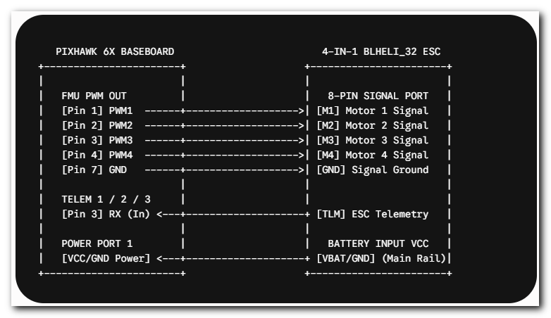
When connecting an FMUv6X architecture board (like the Pixhawk 6X) to a 32-bit ESC (like the Foxeer Reaper or T-Motor P60), you must utilize the I/O PWM Out or FMU PWM Out ports to map your DShot lines correctly to the hardware timers.
Hardware Wiring Configuration
The schematic below maps out the direct interface between the Pixhawk 6X Standard Baseboard and a high-rate 4-in-1 ESC.
Critical Pin Rules for Agile Turning
- Signal Ground Continuity: Do not omit the signal ground wire between the
FMU PWM OUT rail and the ESC signal port. At 400Hz–800Hz DShot frequencies, high-power switching transients from the main battery leads can distort the digital logic unless a dedicated signal ground return pathway is pinned out.
- Telemetry Routing: The
TLM pin from the ESC transmits asynchronous serial data at 115,200 baud. Route this directly to the RX pin of an open telemetry port on the Pixhawk (e.g., Telem 2). This delivers real-time per-motor RPM, voltage, and current arrays back into ArduPilot’s memory.
Core ArduPilot Parameter Framework
To initialize this specific high-speed digital architecture, you will need to push the following adjustments through your Ground Control Station parameter tree:
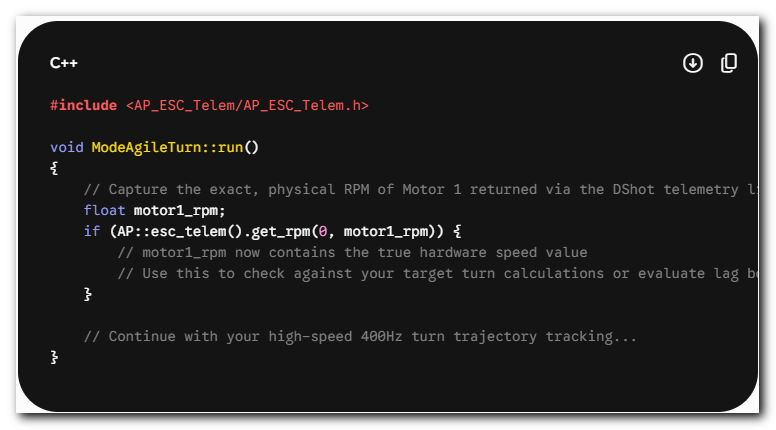
Verifying Telemetry in Code
Once this hardware pipeline is wired up, you don’t have to guess if the motors are keeping up with your custom flight loop. You can poll the filtered RPM feedback directly inside your custom flight mode (mode_agile_turn.cpp) using the underlying AP_ESC_Telem library:
/////////////////////////////////////////////////////////////////////////////////////////////////////
To execute rapid maneuvers with zero float and instantaneous direction reversals, you do not need specialty custom hardware. The physical hardware required is already present in standard 32-bit brushless ESCs. Active braking and reverse rotation are handled at the hardware level by the MOSFET gate drivers and microcontrollers on the ESC, controlled via specific firmware settings.
1. Active Braking (Damped Light / Regenerative Braking)
In older or simpler ESCs, cutting the throttle causes the motor to “freewheel,” meaning the propellers spin down slowly due to air resistance. For agile turning research, this introduces lag.
Modern 32-bit hardware handles this through Damped Light mode (often integrated automatically into modern ESC firmware packages):
- How it works at the hardware level: Instead of letting the motor coast, the ESC’s onboard MCU commands the low-side MOSFETs to intentionally short the motor windings during the off-cycles of the PWM signal.
- The physical result: This actively fights the motor’s momentum, converting the kinetic energy of the spinning rotor back into electrical current (regenerative braking). The motor slows down exactly as fast as your control loop demands.
Top Active Braking Hardware Options:
- Hobbywing XRotor 45A G2: Features Japanese-manufactured MOSFETs and a high-performance 32-bit microprocessor running up to 120MHz. It uses hardware-generated motor PWM combined with native Damped Light Mode for smooth throttle response and immediate deceleration spikes.
- HGLRC Specter BLHeli_32: Built around a dedicated STM32G071 processor, this ESC supports high-frequency PWM up to 128kHz. It includes an integrated CNC aluminum heatsink to safely dissipate the high thermal energy generated by continuous, aggressive braking cycles.
2. Reverse Operation (Bidirectional / 3D Mode)
To reverse a brushless motor, the ESC must instantly change the electrical commutation sequence driving the three motor phases.
- The Hardware Constraint: Reversing a motor mid-air creates massive voltage spikes (back-EMF) and huge mechanical torque loads. To handle this without destroying the circuitry, you need an ESC with robust TVS (Transient Voltage Suppressor) diodes or a high-quality external capacitor soldered to the main power pads.
- The Firmware Constraint: You must configure the ESC into Bidirectional Mode (also known as 3D Mode). In this configuration, ArduPilot treats the midpoint of the signal channel (e.g., 1500µs) as “zero RPM.” Sending a signal above 1500µs spins the motor forward; sending a signal below 1500µs forces the ESC to brake the motor to a complete stop, change phase firing order, and accelerate it backward.